Resistance Welding Transformers Manufacturer & Exporter
Custom manufacturer of resistance welding transformers specializing in automated resistance welding equipment featuring spot, projection, rocker arm, butt, seam, bench, gun, 3-phase, mil spec, MFDC & HFDC & miniature welders. Custom design of tooling & fixtures. Consumable products include electrodes, seam wheels, caps, shanks, holders, controls, cables, coolers, chillers & peripheral equipment. Remanufactured & special application equipment as well as service, training, parts & supplies.
Resistance Welding Process Perfectors; Producers Of R/W Equipment. Wholesale Distributors Of All R/W Components & Raw Materials: RWMA Classes 1-14. Special Machined Parts & Tooling. Evaluations & Sample Welds Performed transformer design and characteristics would have been a rather controversial subject 15 years ago, as in those days the name-plate kilovolt-ampere rating of the transformer meant little other than that it was printed in English

Often times in the early years, if the power companies limited the maximum connected kilo volt-amperes for a particular installation, a machine was supplied with this name-plate kilovolt-ampere rating, regardless of the actual load drawn by the machine. It was rather common practice to use excessive amounts of copper in the secondaries and a very small amount of primary copper.
There was no logical reason for this except perhaps that the secondaries could be seen while the primaries were covered. In general, confusion existed, no standard ratings were used, and it was extremely difficult for power companies or users to determine actual ratings and demand figures.
This condition of course could not continue and several years ago the AIEE and the Resistance Welder Manufacturers' Association (RWMA) drew up specifications for the standardization of welding transformer ratings. designs and builds new resistance welding transformers. The transformers range in designs from single-phase AC, three-phase DC, also provides rebuilds, remanufacturing and repairs on all welding transformers. Transformers are completely disassembled and inspected for damage before the repair process begins. Upon completion of the repair, welding transformers are fully tested to ensure proper operation.
Design & Manufacturing
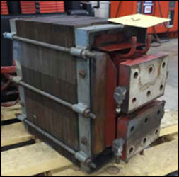
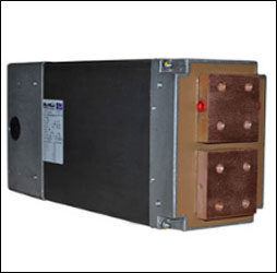
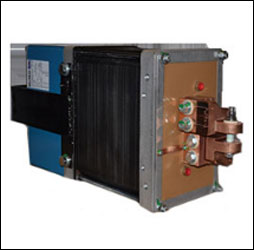
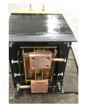
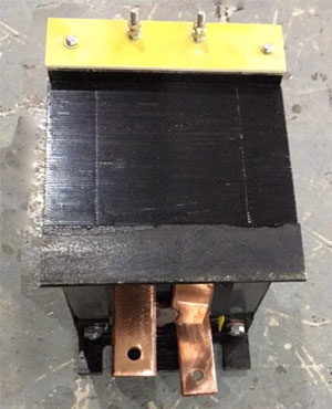
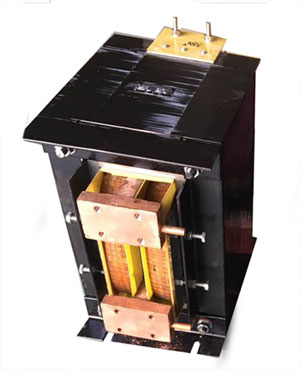
Our water-cooled welding transformers are designed to deliver power at high efficiency with low impedance. Energy loss is minimized by the use of stacked silicon steel cores. Secondaries are cast of highest quality copper with non-corrosive copper water-cooling tubes brazed or cast to the outer edges of the secondary sections. This eliminates excessive rise in temperature under continuous demanding service. Primary coils are wound of copper ribbon insulated between turns and double wrapped. The coils are dipped in a moisture-, heat-, and oil-resistant varnish and then baked. That process is repeated twice for optimum effect. When finished, the entire transformer assembly is also dipped and baked in the same varnish solution.
Transformer Options:
Applications :
Machine Type :
Applications : Predominantly used in press, seam, or rocker arm welding machines.
Features :
Ratings : 20 to 600 KVA
Heat generation is the inherent function and benefit of the resistance welding (RW) process. The heat is generated by an electrical current, which is controlled and transmitted by electrical components. As a result, there will be a constant effect manifested by a rise in temperature that, without proper cooling, will affect the system’s electrical components. To avoid this scenario, proper electrical component sizing and proper water cooling are the best means of protection for RW transformers and MFDC transformer rectifiers from over-temperature—thereby ensuring safety, quality, and uptime. While there are many facets to RW machines, the answers to the “how to” question will focus on elements that are most closely related to protection from over-temperature.
Protecting RW transformers and MFDC transformer rectifiers.
There are several elements that play in the equation of protecting RW transformers and MFDC transformer rectifiers, including :Electrical Component Sizing
The electrical components that transfer energy to the weld include electrodes, adapters, busbar, cabling, transformer or MFDC, welding control, circuit breakers, fuses, and primary wiring. These electrical components require proper sizing.Water Cooling
To keep electrical components within rated temperature limits, it is important to properly size and cool electrical components to ensure operation within rated temperature limits. Water cooling is the most effective means to keep electrical components within rated temperature limits.Water Cooling Specifications
Common water cooling specifications include maximum inlet temperature in degrees (86°F or 30°C), pressure differential in pounds per square inch (lb/in.2) or bars, and especially flow rate, in gallons per minute (gal/min) or liters per minute (L/min).Sensors
A resistance welding production line, with any combination of manual and automated processes, relies on the proper application and feedback of sensors to ensure safety, quality, and uptime. Without sensors, any manual or automated process could be easily crippled.Flow Switch
The most effective solution to provide needed protection against serious damage from over-temperature is the rapid alert flow switch sensor. Best located in the “water out” circuit, the flow switch sensor offers the best protection against over-temperature of electrical circuit components due to sudden loss of cooling water.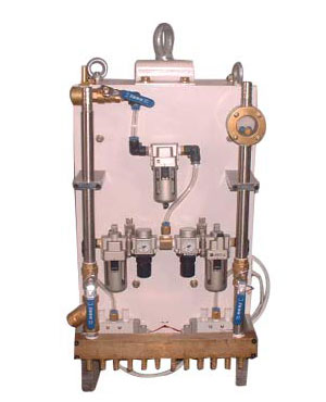
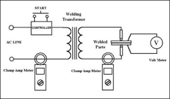
The tests described below utilize an ohmmeter. A regular unit will pick up most shorts, but a mega-ohm meter, if available, will work better. Later steps also ask you to use a fused 110 VAC power cord. Make sure the cord is fused with a ~5 amp fuse. As always, exercise due care and caution when working around live electricity.
1. Make sure that the power to the welder is disconnected and the power is locked-out according to plant approved lockout-tagout procedures.
2. Disconnect the line leads running from the transformer or tap switches to the control.
5. Make sure that the weld tips, or secondary of the transformer is an open, not complete, circuit. This can be accomplished by placing a piece of rigid insulation or an old credit card between the tips.
6. Connect the fused 110 VAC cord across the two line leads. Note: If the windings of the transformer are bad, you will probably blow the fuse in the 110V cord.
Check the Secondary output voltage of the transformer with a voltmeter. This measurement should be made right at the transformer, and not at the tips. Bad connections in the secondary loop could cause a larger voltage drop across them. Also make sure that the secondary loop is still open (above) or the transformer will be under a load.